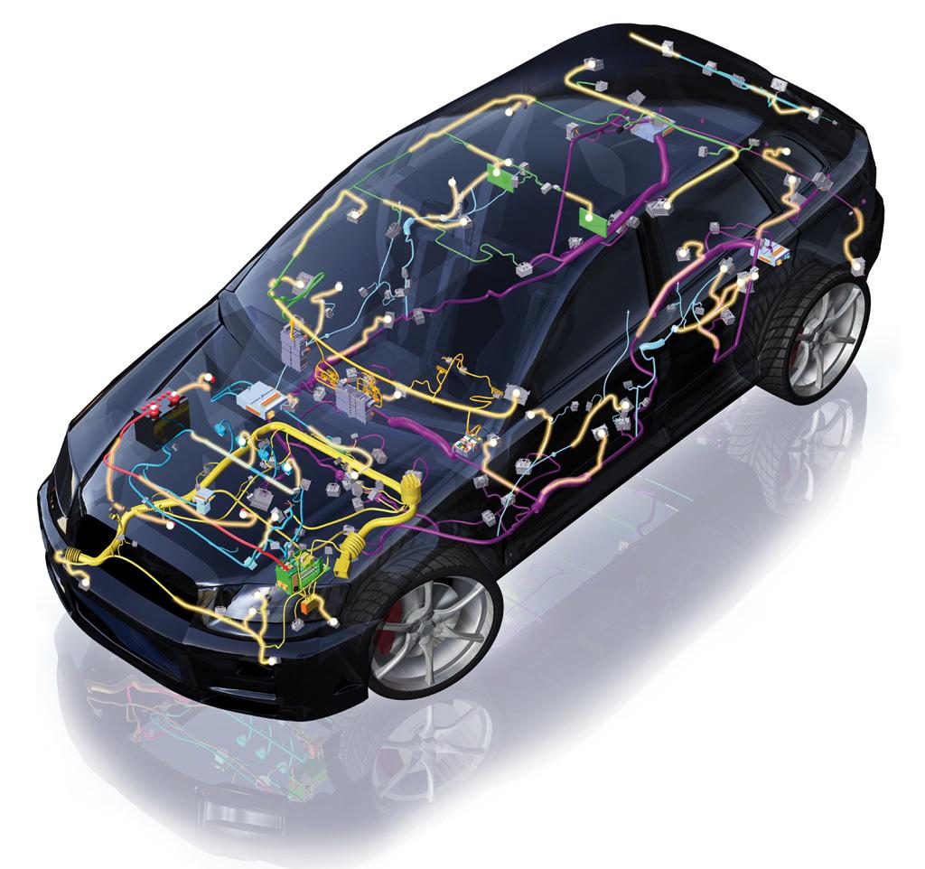
Testing of on-board network architectures
Customer: Ford Research and Innovation Center Aachen
Area: Automotive industry / R&D
Requirements: Testing of on-board network architectures with voltages up to 60 VDC
Implementation: Software: LabVIEW
Testing on-board network architectures
In cooperation with the Ford Research and Innovation Center Aachen, we realized the first stage of a test bench for testing on-board network architectures with voltages up to 60 VDC.

Up until recently, the on-board network on most vehicles consisted of an alternator and a single 12-volt lead-acid battery that was “simply” connected to a network of cables with just a few electrical consumers. The introduction of start-stop systems and other measures to reduce fuel consumption as well as numerous additional electrical consumers, such as driver assistance systems, required new solutions. Today, “intelligent” concepts are utilized in which the components of the on-board network interact by means of bus systems. To allow for the testing of currently used and future components both individually and in combination, including for operation with 48 volts, measX developed a variable test system for Ford.
The first step laid the foundation for comprehensive and variably configurable tests on batteries. In order to accomplish this, it was necessary to connect the battery management system (BMS) present in many modern energy storage systems over a CAN bus. This allows the battery to be woken up, if necessary, to access various types of measurement data. Project-specific signal conditioning with various connections for electrical signals was also developed. The system now offers 16 analog inputs and 4 analog outputs of different voltage ranges as well as 14 connections for type K temperature sensors, 8 optically isolated 24V digital inputs and 8 freely assignable normally open contacts, all electrically isolated from each other.
Interfaces for simulation models
The test setup to be investigated can be supplied with a combination of programmable electronic power supplies and loads up to 510A and loaded with a maximum of 1200A. A spacious climate cabinet allows the investigation of test samples under extreme ambient temperatures and protects the test chamber in the event of battery defects by means of its integrated vacuum and extinguishing functions.
In order to integrate additional environmental variables, calculations and control options, an interface to simulation models was implemented. Any models can be integrated, such as from MATLAB/Simulink.
The tests can be controlled either manually or automatically via test scripts that can be composed from predefined individual steps, parameterized and modified by the user. It is also possible to integrate various IOs provided via CAN or simulation models.
The operating software for the test bench supports the creation of scripts, configuration of the complete system, integration of CAN databases and simulation models, parameterization of measurement channels, configuration of the mapping of important control and monitoring channels and specification of test specimen parameters. To simplify daily workflows, the complete configuration can be saved, loaded or imported in sections.
The actual control of the test bench hardware, the data acquisition, the processing of test scripts, the execution of the simulation model and the constant monitoring of various limit values are carried out on a PXI industrial PC with a real-time-capable operating system, currently clocked deterministically at 1 ms.
In the first development stage of the battery tester, it supports the testing of batteries. Work is currently underway on adding functions for testing electric drives and generators as well as DC/DC converters so that combined system tests are also possible.
Image: © Delphi
Download X-Press with the report as PDF


